Windows Wi-Fi Driver RCE Vulnerability – CVE-2024-30078
In June, during “Patch Tuesday”, Microsoft released a fix for CVE-2024-30078. The severity of this vulnerability was marked as important, with its impact set to Remote Code Execution (RCE).
After reading Microsoft’s bulletin, this vulnerability piqued our interest. It seemed plausible for an unauthenticated attacker to send a malicious packet to an adjacent system, which could enable remote code execution. Even if an attacker must be within proximity of the target system to send and receive radio transmissions to exploit this vulnerability, an over-the-air RCE seemed too cool to skip.
Our analysis was performed under Windows 11, Version 23H2.
Binary Diffing
The vulnerability is located in the nwifi.sys Wi-Fi driver. We used BinDiff to compare the two versions of this driver:
- V.10.0.22621.3527 – vulnerable:
SHA1 788E6FD6D60F3CD5A6FAC5C14883A4A3EF53A355 - V.10.0.22621.3733 – patched:
SHA1 BF5871100143804B77185314BD4DD433AFAC816B
The patch was applied in the function named Dot11Translate80211ToEthernetNdisPacket() :
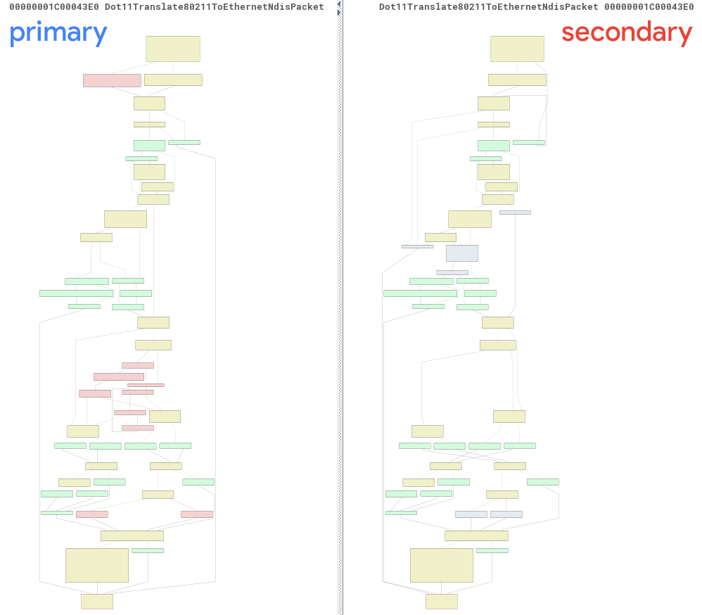
In the patched version, the following additional check has been added:
![]()
Call Graph
In the call graph of the Dot11Translate80211ToEthernetNdisPacket() function, we can see how the vulnerable function is reachable from both Access Point (AP) and Station (STA) mode.
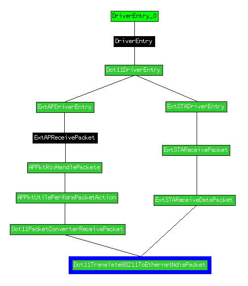
Please Note: here, IDA’s graph is not right as the ExtSTAReceivePacket() function is not directly called but just referenced.
Access Point Mode (AP): this is also known as hotspot mode. In this mode, the Wi-Fi module acts as an access point, similar to a router’s functionality. It creates a wireless network, allowing other devices to connect to it.
Station Mode (STA): STA mode allows the device to connect to an existing wireless network. It turns the device into a client of an existing wireless network, enabling access to the Internet or communication with other devices. In STA mode, the device becomes a node on the network, facilitating data exchange and communication with other devices.
We decided to focus on the STA path as it’s more interesting for our use case.
Static analysis
The nwifi.sys driver is an NDIS Filter Driver. It is placed in the driver stack between protocol drivers and miniport drivers. Its intended usage is to monitor and modify (if needed) packets coming from or to the Wi-Fi and pass them to the next driver in the stack.
The driver has to register callbacks with the NdisFRegisterFilterDriver() routine. The most interesting callbacks are the AttachHandler and ReceiveNetBufferListsHandler.
The ReceiveNetBufferListsHandler callback in this driver is present in the Pt6Receive() function; it receives packets from the underlying drivers.
Even if, for some reason, IDA does not show this in the function graph above, we could verify it dynamically in WinDbg. The actual call stack looks like this:
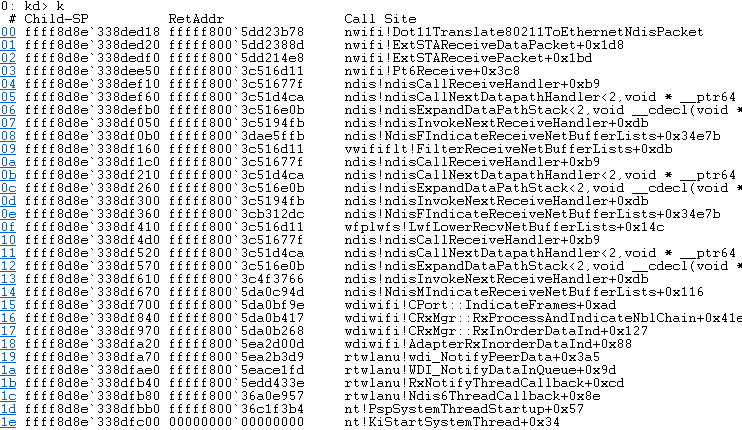
Pt6Receive() receives a pointer to a NET_BUFFER_LIST structure (NBL) that consists of our packet. It then calls the ExtSTARecvInitializeMSDUFromNBL() function in order to convert the NBL structure to a structure called MSDU.
The MSDU structure looks like the following snippet:
struct MSDU_struct {
 uint64_t info6;
 char flags;
 uint32_t llc_offset;
 uint32_t data_length;
 uint32_t field_14;
 uint64_t data_begin;
 NET_BUFFER_LIST *nbl;
 _MDL *first_mdl;
 _MDL *last_mdl;
 uint32_t offset;
 uint32_t nbl_data_length;
};
Later, the MSDU structure is passed to the Dot11Translate80211ToEthernetNdisPacket() function via ExtSTAReceivePacket() and ExtSTAReceiveDataPacket().
The function name makes it obvious that it’s translating IEEE 802.11 packets to Ethernet packets. The function gets the MSDU structure as its second argument. This structure has a pointer to the first _MDL from the incoming _NET_BUFFER_LIST, which contains the packet to be translated. The translation is done by formatting the ethernet header in front of the next layer. The translation happens inside the same memory area where the original packet was placed.
The bug
After some reverse engineering, the patch becomes more understandable. The Dot11Translate80211ToEthernetNdisPacket() function reads the LLC packet’s header in order to understand the next layer in the packet. Before it reads the LLC header, it checks if the packet’s buffer has enough data. LLC header size is 8 bytes:

The check is present in the code as follows:
![]()
In case the next layer is VLAN, there should be an additional 4 bytes of IEEE 802.1Q header, and these 4 bytes also have to be present in the packet:
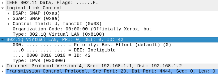
In the vulnerable version, there is no check if these 4 bytes of the IEEE 802.1Q header are present. The check, however, has been added in the patched version, as can be seen in the below image:

In the vulnerable version, if LLC->Type == 0x8100 and there is no data after the 8 bytes of LLC, there will be an out-of-bound read (case #4). The overwrite happens in the part of the code that builds the ethernet header:
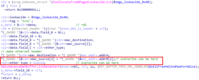
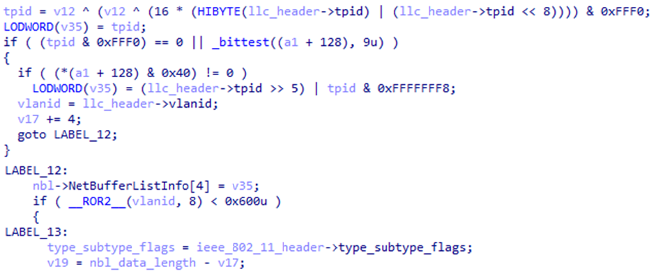
Variable v17 is the offset to where the ethernet header must be built. The offset of the ethernet header (v17) is calculated depending on the values in the LCC and IEEE 802.1Q headers. There are four different cases where an ethernet header can be placed:
- Case 1:
LCC->type != 0x81 && LCC->type < 0x600
In this case,v17will be equal toLCC offset - 0xEand the ethernet header will be built before the LCC header:

- Case 2:
LCC->type != 0x81 && LCC->type >= 0x600
In this case,v17is equal toLCC offset - 0xE + 8and the ethernet header will rewrite the LCC header:

- Case 3:
LCC->type == 0x81 && vlanid < 0x600
In this casev17 = LCC offset - 0xE + 4. The ethernet header will rewrite half of the LCC header:

- Case 4:
LCC->type == 0x81 && vlanid >= 0x600
That is what we need! In this case,v17 = LCC offset - 0xE + 4 + 8and the rest of the ethernet header will be written outside, on memory described by_MDL:

Ufortunately, the buffer where the packet is placed has additional limitations, which we cannot control.

The IEEE 802.1Q header’s field tpid is checked, and the vlanid field must be right. The Dot11Translate80211ToEthernetNdisPacket() function checks the IEEE 802.1Q header, and we cannot control this field. Also, there is no guarantee that these bytes will be useful.
Dynamic Analysis
To confirm our analysis, we checked everything dynamically, sending packets over Wi-Fi to a vulnerable machine.
As pointed out in Microsoft’s bulletin, an attacker does not need authentication on the target system. However, for the packet to be delivered, we have to be on the same Wi-Fi network as the target; otherwise, the underlying drivers will block the packets.
There are several options on how to perform the attack:
- Set up a fake AP with the same configuration that the target uses. In this case, the target will automatically connect to our AP;
- Connect to the same AP as the target: this route limits this attack to public networks or will require the key of the AP to be brute-forced/known. Besides that, there’s another fundamental reason not to take this path. Traffic from the network where other devices are present will make it harder to predict which packets the target catches. For example, if we use a spraying technique, we will not be sure that all the packets sent to the target are in the suitable memory layout for the attack to be successful.
Fake AP
Since we need to be able to send raw packets via Wi-Fi first, for our tests, we have built a fake AP with Python and the scary library. It is fast enough to be used to develop and prototype, allowing us to send raw packets over Wi-Fi.
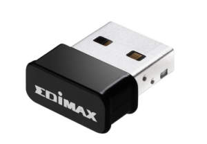
Our setup included two VMs: a Windows 11 23H2 and a Kali Linux machine. Both have connected AC1200 Wi-Fi 5 USB adapters.
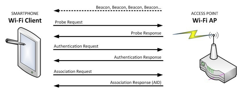
Our AP has to do the following minimal things:
- Beaconing: sending beacon packets to inform stations about our presence. A beacon packet has to be sent every 102.4ms;
- Response to probe packets (broadcast and direct);
- Response to authentication requests. For our tests, no authentication is required, so we used Open System Authentication;
- Response to association requests.
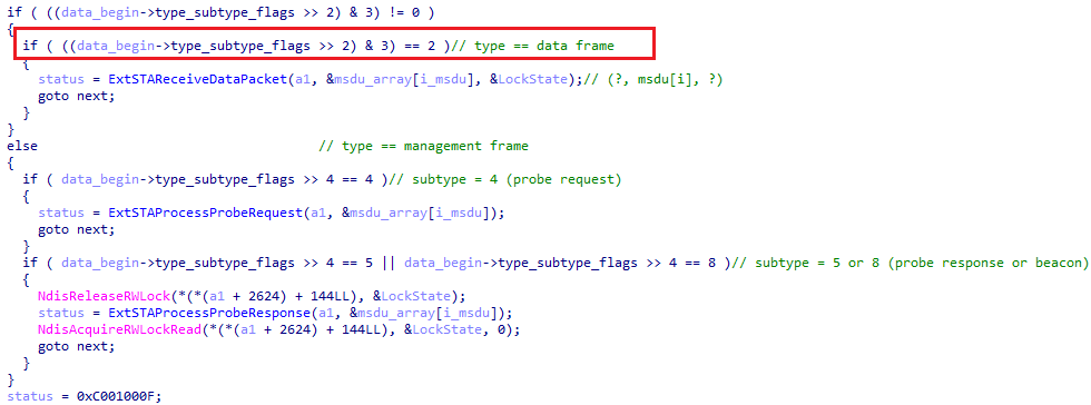
After association, the station requests network info using DHCP, ARP and other protocols. These packets are sent as data packets. Our payload also has to be sent as a data packet in order to be able to reach our target function:
Payload (data) packets can be generated with the following snippet:
def send_payload_v1(self, destination, with_vlan):
 radiotap = RadioTap()
 dot11 = Dot11(type = 2, subtype = 0, addr1 = destination, addr2 = self.ap.mac, addr3 = self.ap.mac, SC = self.ap.next_sc(), FCfield='from-DS')
 llc = LLC(dsap=0xaa, ssap=0xaa, ctrl=0x03) / SNAP(OUI=0x000000, code=0x8100)
 packet = radiotap / dot11 / llc # here can be any additional bytes if needed
 sendp(packet, iface=self.ap.interface, verbose=False)
Debugging
Now that we have everything ready to try our attack dynamically, we have to set the breakpoint on the vulnerable function (Dot11Translate80211ToEthernetNdisPacket()), start the fake AP and connect to it. After STA successfully pass all the connection steps, the breakpoint is hit:
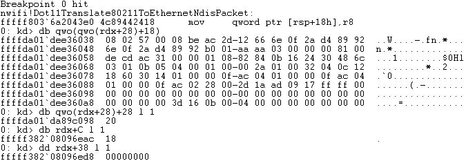
In the image above we can see our packet; it has a length of 0x20 bytes. The IEEE 802.11 header is placed at offset 0x00 while the LLC header is placed at offset 0x18.
We can also see that LCC->type is 0x81, so we should pass the code that checks the IEEE 802.1Q header, namely the tpid field. Even so, the tpid value does not pass the checks, so this packet will not be translated.
The 12 lower bits of tpid must be 0 for the packet to be translated.
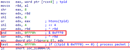
In this code, the overread has already happened (first instruction in the above picture).
We could spray packets with proper values and right size and then send the vulnerability-triggering packet. It sounds nice, but it’s difficult to catch the real attacking packet in the debugger. So, we simulated the condition where the bytes are rightfully set after our attacking packet.
For the simulation another packet was sent, and the buffer behind it was edited to create the perfect condition to trigger the vulnerability.
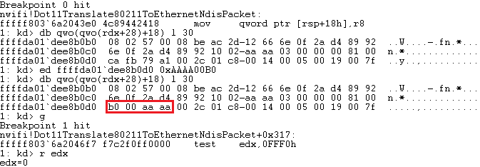
As you can see from the below images, this allowed us to bypass the tpid check. It will also help to get to the right path at the vlanid checking to increase ethernet offset to 8:

The code vulnerable to the out-of-bound write is shown in the following picture. Here, you can see that the rcx register is set to the pointer where the ethernet header has to be built. The last three instructions build the ethernet header. In theory, the overflow will occur at the last two instructions:
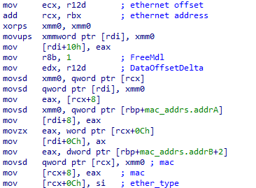
Straight before the vulnerability is triggered, the memory layout looks like the following:

Here, we can see at which address the ethernet header will be built. Underlined in red are the bytes which the overflow will overwrite.
After these three instructions have been executed, the memory layout looks like this:
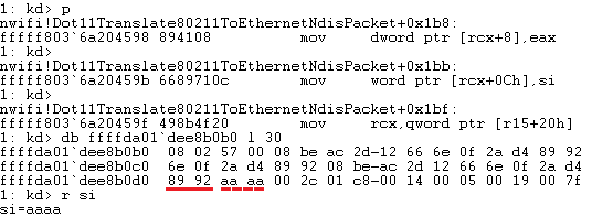
Here, we can see that the first 2 bytes have been overwritten with the end of the source MAC address, which is under the attacker’s control. The following two bytes are left unchanged because the si register has the same value and is read from the same place.
Exploitability
First of all, to get the overwritten state, we need to be very lucky and have proper bytes behind the packet buffer, which will pass tpid and vlanid checks. We do not control these bytes within the packet, which leads to overwriting. We can probably use a spraying technique before sending the vulnerability-triggering packet, but there are other limitations:
- In order to exploit this vulnerability, we need some form of information leaking vulnerability, which is currently lacking.
- The memory, which is overwritten, is also crucial. It should be something useful like some pointers. But this buffer does not contain anything useful. If we check this buffer with the
!addresscommand, it will give the following result:
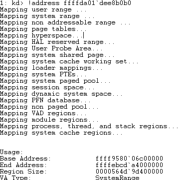
This memory region looks strange (e.g. Region Size). Checking this memory region with RamMap shows the tag of the memory:

While if we try to check this memory with the !poolused 4 command, it will show us that the tag is unknown.

The only thing left is to understand what this memory region is, putting a breakpoint on its allocation.
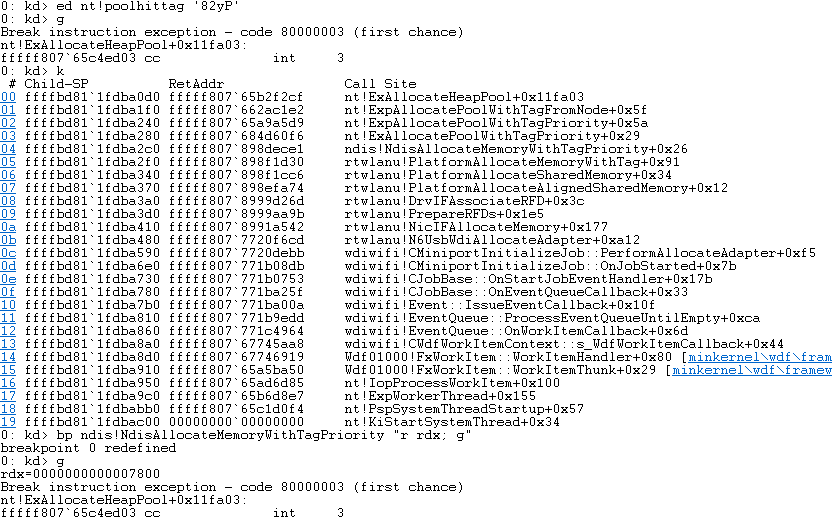
That gives us an idea of how the memory is allocated; it is allocated when connecting an adapter to a system and freed on its disconnection. The allocated buffer size is 0x7800.
Conclusion
Upon analysis, the impact of this vulnerability seems much less critical than what Microsoft anticipated. We can only overwrite another packet (limited number of bytes) if it is placed straight after our one, which is very unlikely and useless, as no interesting data there can be leveraged to take control of the execution flow. Anyway, we would love to be proven wrong, as this seems a very cool exploitation vector.


